

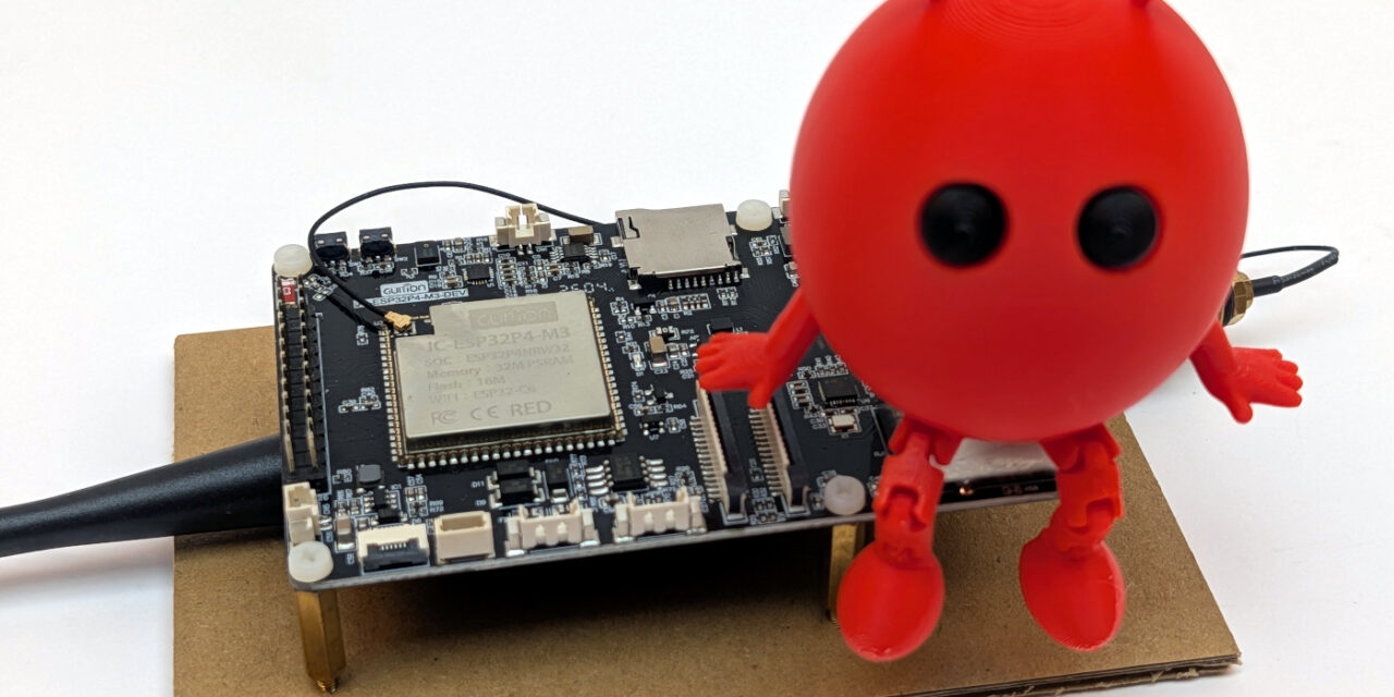
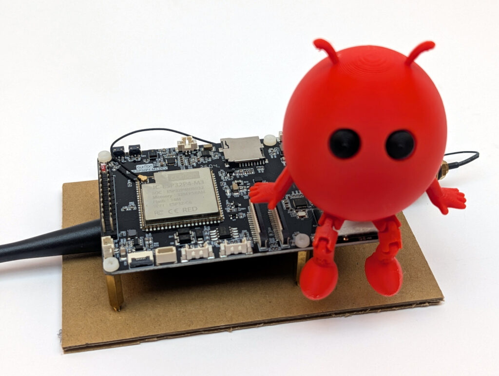
After I showed you in Part 2 of my ESP-Claw series how I compiled ESP-Claw for the first time, today we move on to what is probably the trickiest part of the whole project: How do I get ESP-Claw to recognize my Guition JC1060P470 as a supported board?
Anyone who read Part 2 knows: my successful build was configured for the ESP32-P4 Function EV Board. Espressif’s own reference board. If I were to flash this firmware as-is onto my Guition, the display, touch, audio, and WiFi wouldn’t be addressable because the pin assignment is completely different. So I needed my own board adaptation.
This story has a classic turning point. First a longer period of being stuck, since I hadn’t done such an adaptation in a while, then the obvious idea of using an unassuming search term in GitHub’s own search and suddenly the path was clear.
ESP-CLAW board adaption
What exactly is a board adaptation in ESP-Claw?
ESP-Claw ships out of the box with a few reference boards that work right away:
- ESP32-P4 Function EV Board (Espressif’s own development board)
- M5Stack Tab5 (a 5-inch HMI board with ESP32-P4)
- Waveshare ESP32-P4 Nano
- Various others from Espressif and third parties
My Guition JC1060P470 is not among them, but in return it was also cheap to get on AliExpress. For ESP-Claw to know how to deal with the hardware – which pins for I²C, which for SDIO to the WiFi co-processor, which LCD controller is installed, how the audio codec is addressed and so on – it needs a tailor-made configuration. ESP-Claw calls this configuration a board adaptation, and it consists of several files, none of which were provided directly by the manufacturer in the download data offered for the board:
| File | What it defines | Format |
board_info.yaml |
Metadata about the board (name, manufacturer, chip) | YAML |
board_peripherals.yaml |
Hardware peripherals (I²C, I²S, GPIO, LDO, DSI, LEDC) | YAML |
board_devices.yaml |
Logical devices (audio codec, display, touch, SD card) | YAML |
setup_device.c |
Driver-specific C code (e.g. JD9165 init sequence) | C |
sdkconfig.defaults.board |
Defaults for ESP-IDF (flash size, PSRAM, ESP-Hosted) | Kconfig |
README.md |
Documentation for other makers | Markdown |
Sounds manageable. But the catch is: for each of these files, I had to know what exactly is built into my board and which pins it communicates with. And with an AliExpress board carrying Chinese documentation, that was the first real stumbling block.
The dead end: data sheet research
My first instinct was to look for a data sheet in the AliExpress listing. A wasted effort. The seller only had a few marketing images online. On the manufacturer’s website at Guition I did find a PDF, but it was in English and Chinese and mostly showed connector pinouts, not the internal pin assignments of the ESP32-P4 to display, touch or audio.
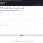
Here’s another link to the manufacturer’s info, which turned out to be quite helpful: https://devices.esphome.io/devices/guition-esp32-p4-m3-dev/
This ZIP file contains schematics (in Chinese), demo code (Arduino-based, not directly usable) and a few PNG screenshots. Helpful, but not enough to build an ESP-Claw adaptation from.
Here’s the link to the ZIP file mentioned above (use at your own risk): https://pan.jczn1688.com/directlink/1/HMI%20display/JC-ESP32P4-M3-DEV.zip
ESP-Claw’s own documentation also only helped to a limited extent: it describes the YAML schema, but without a complete example for an exotic display controller like the JD9165, you’re on your own.
I spent longer than I’d like to admit reading through ESP-Claw’s reference boards:
boards/espressif/esp32_p4_function_ev/for the P4 MIPI-DSI setup with EK79007boards/m5stack/m5stack_tab5/for a P4 with a different display controller (ILI9881C)
From both I could learn structure and schema, but not the specific JD9165 init sequence or the exact pin assignments of my Guition board.
The breakthrough: a GitHub search for “JC1060P470”
Frustrated, I finally tried what should actually always be the first step: a global GitHub search for the exact board name.
Link: https://github.com/search?q=JC1060P470&type=code
And indeed. The search surfaced a rather unassuming repository:
I built on this repository: https://github.com/Deep-start9527/guition_product_demo
A maker had published a complete demo project for the JC1060P470 in ESP-IDF here, with fully working code for display, touch, audio and more. Exactly the information that had been missing from Guition. That was my moment of hope.
Here is another repository that the manufacturer has linked on its product page: https://github.com/p1ngb4ck/unofficial_guition_esp32p4_repo/tree/main/JC-ESP32P4-M3-Dev
From this repository, two files became my most important allies:
pingcfg.h– the complete pin map of the board, neatly documented as header constantsdemo/main/lcd/lcd.c– the JD9165 init sequence, around 50 register writes with comments
The pin map from pingcfg.h
From the pingcfg.h, I was able to extract the complete pin assignment. Here’s a condensed overview of the most important connections:
| Function | Pin(s) | Usage |
| I²C (touch + audio codec) | SDA=7, SCL=8 | GT911, ES8311 |
| I²S (audio) | MCLK=13, BCLK=12, WS=10, DOUT=9, DIN=48 | ES8311 microphone/speaker |
| Audio amplifier | PA_EN=11 | Speaker amp on/off |
| LCD backlight | BL=23 (LEDC, 20 kHz) | Brightness control |
| LCD reset | RST=0 | Hardware reset of the panel |
| microSD (4-bit mode) | CLK=43, CMD=44, D0–D3=39/40/41/42 | SDMMC |
| ESP32-C6 SDIO | CLK=18, CMD=19, D0–D3=14/15/16/17, RST=54 | ESP-Hosted for WiFi/BT |
| UART0 (console) | TX=37, RX=38 | Serial output via CH340 |
With this project in hand, the 6 empty configuration files suddenly became a manageable task. I now knew what was connected where, and that’s half the battle.
Phase 1: Create the directory structure
ESP-Claw expects board adaptations under the path application/edge_agent/boards/<manufacturer>/<boardname>/. In my case:
Command: mkdir -p D:\esp32-claw\esp-claw\application\edge_agent\boards\guition\jc1060p470_m3_dev
I chose the suffix _m3_dev because the board is officially called JC-ESP32P4-M3-DEV. This way, the directory name stays consistent with the manufacturer’s designation.
Phase 2: board_info.yaml – the board’s business card
The easiest file. It only contains metadata that ESP-Claw uses to list the board in its selection:
- Board name (internal and for display)
- Manufacturer (Guition)
- Chip family (esp32p4)
- Hardware revision
This file takes maybe 20 lines and is done in five minutes thanks to the LLMs of this world.
Phase 3: board_peripherals.yaml – the hardware layer
This is where it gets interesting. In this file, I define all the hardware peripheral blocks of the ESP32-P4 that ESP-Claw should later use. For my board, that meant 7 peripheral definitions:
- i2c_master – the I²C bus for touch and audio codec
- i2s_audio_out – I²S channel for DAC (speaker)
- i2s_audio_in – I²S channel for ADC (microphone)
- gpio_pa_control – control GPIO for the audio amplifier
- ldo_mipi – the internal power supply for MIPI-DSI
- dsi_display – the DSI bus for the display
- ledc_backlight – LEDC PWM channel for the backlight
With the first versions of my YAML file, the build immediately ran into schema errors. ESP-Claw is very strict when parsing, and I had to figure out in several iterations which field names are actually expected. Here are the most important corrections I learned from my first failed attempts:
| My first assumption (wrong) | What ESP-Claw really expects |
type: mipi_dsi |
type: dsi |
num_data_lanes: 2 |
data_lanes: 2 |
type: touch |
type: lcd_touch |
| I²S as a single peripheral block | Split into i2s_audio_out + i2s_audio_in |
My tip: Have a look at the YAML of an existing similar board from the ESP-Claw project (e.g. esp32_p4_function_ev) and copy the structure before inventing your own field names. That saves an enormous amount of time.
Phase 4: board_devices.yaml – the logical layer
While board_peripherals.yaml describes the raw hardware, board_devices.yaml defines the logical devices that run on top of that hardware. So: Which display driver? Which audio codec? Which touch controller?
For my board, this was originally 6 devices:
- audio_dac – ES8311 as DAC for audio output
- audio_adc – ES8311 as ADC for microphone input
- fs_sdcard – FAT file system on the microSD card
- lcd_brightness – brightness control via LEDC
- display_lcd – the actual display with JD9165 controller
- lcd_touch – GT911 touch controller
An important insight: WiFi and Ethernet are NOT included here. ESP-Claw configures the network entirely via the Kconfig defaults in sdkconfig.defaults.board, not via YAML. That confused me at first because I had been looking for a “wifi” entry.
Phase 5: setup_device.c – the JD9165 init sequence
This is where the most exciting part came in. Display controllers like the JD9165 require a specific initialization sequence of around 50 register writes. This sequence isn’t in any data sheet, only in the board’s vendor demo. Without it, the display only shows pixel garbage or stays black.
This is exactly where the lcd.c from the Chinese demo project saved my life. I could take the entire init array 1:1 into my own setup_device.c:
- Page-select commands (for choosing internal register banks)
- Power sequencing
- Gamma correction
- Timing parameters for the DSI interface
- Display-on command with a 120 ms wait
Reconstructing this sequence myself would probably have cost me days and, without a logic analyzer or MIPI sniffer, would have been practically impossible.
My takeaway: When dealing with exotic display controllers, always look for an existing vendor demo before trying to derive the init sequence from the data sheet. Data sheets describe registers, but not the correct order or timings.
Note: I then ended up commenting all of that out again because, after flashing, the microcontroller was stuck in an endless loop, since it couldn’t find a display. I don’t have one yet.
Phase 6: sdkconfig.defaults.board – the ESP-IDF defaults
In this file, I set the ESP-IDF-specific defaults for my board. Here are the most important entries:
CONFIG_ESPTOOLPY_FLASHSIZE_16MB=y(16 MB flash)CONFIG_SPIRAM_MODE_HEX=y(Octal PSRAM)CONFIG_SPIRAM_SPEED_200M=y(PSRAM at 200 MHz)CONFIG_PARTITION_TABLE_CUSTOM_FILENAME="partitions_16MB.csv"CONFIG_ESP_HOSTED_HOST_INTERFACE_SDIO=y(WiFi via C6 over SDIO)CONFIG_ESP_CONSOLE_UART_DEFAULT=y(console via UART0)
This file is exactly what activates the ESP-Hosted bridge to the ESP32-C6, which I need later for WiFi. Without this setting, the P4 cannot communicate with its radio co-processor.
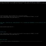
Phase 7: Letting the ESP Board Manager generate the code
ESP-Claw ships with a helpful tool called the ESP Board Manager, which automatically generates C code from my YAML files. I call it once after each change to the YAMLs:
Command: idf.py gen-bmgr-config -c ./boards -b jc1060p470_m3_dev
If everything fits, I see output like this at the end:
Successfully validated 7 peripherals
Successfully validated 6 devices
If the numbers match what I have defined in YAML, the adaptation is syntactically correct. If something is wrong, you usually get a very clear error message – with line number and a concrete hint. The error messages are understandable once you’ve wrestled with the configuration a bit beforehand…
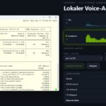
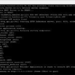
Phase 8: Build and first tests
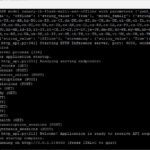
After all this preparation, the decisive moment arrived:
Command: idf.py build
The first attempt, as expected, threw errors like missing fields, wrong data types, and forgotten dependencies: blocks. But after every correction I got a little further, until finally a clean build went through:
edge_agent.bin binary size 0x28e3a0 bytes. Smallest app partition is 0x400000 bytes. 0x171c60 bytes (36%) free.
About 2.6 MB of firmware for my specifically adapted board. Ready to flash.
My personal conclusion on Part 3
Writing a board adaptation for a board that isn’t officially supported isn’t a free ride. There were several moments when I was close to moving the project to an ESP32-P4 Function EV Board just so I wouldn’t have to wrestle with the Guition anymore.
What ultimately helped me was:
- The GitHub search for the exact board name. It turned hours of guessing into concrete pin maps and init sequences.
- The ESP-Claw reference boards as a template. Even though none of them exactly matched mine, the structure was very instructive.
- Patience with the iterative YAML schema learning. Every schema error was a step toward understanding.
- Not trying to reconstruct the JD9165 init sequence myself. When someone has spent hours in front of a logic analyzer before you, gratefully use the result.
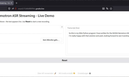
These three parts of my series (installation, build, board adaptation) are the “boring but” necessary basics. They were most of the work, but they’re also the foundation for everything exciting that follows. From Part 4 onwards it gets much more entertaining, because that’s when the AI part comes into play.
In the next part, I’ll show you how I connect my ESP-Claw agent to my own Ollama inference server. How I set the right configuration fields in the web UI, and which stumbling blocks were waiting for me. Spoiler: there were some.
See you in the next part!
What’s coming in the next posts?
- Part 1: Kickoff and introduction of the vision
- Part 2: Setting up ESP-IDF v5.5.4 and building ESP-Claw – step by step
- Part 3 (this post): Adding a new board to ESP-Claw – my board adaptation for the Guition JC1060P470
- Part 4: Connecting ESP-Claw to your own Ollama server – configuration and first chats
- Part 5: Understanding capabilities and skills – the architecture of an ESP-Claw agent
- Part 6: Writing your own skill – remote-controlling the robot car or explaining the dishwasher
- Part 7: Voice in, voice out – the HMI board as a real voice assistant to help out at the washing machine
- Part 8: Lua scripts for behavioral patterns – when the agent acts on its own

The tutorial offers a clear and practical guide for setting up and running the Tensorflow Object Detection Training Suite. Could…
This works using an very old laptop with old GPU >>> print(torch.cuda.is_available()) True >>> print(torch.version.cuda) 12.6 >>> print(torch.cuda.device_count()) 1 >>>…
Hello Valentin, I will not share anything related to my work on detecting mines or UXO's. Best regards, Maker
Hello, We are a group of students at ESILV working on a project that aim to prove the availability of…